As can be seen between posting dates, I have taken a significant amount of time from posting to this blog. As career responsibilities change, my time spent directly on the software fluctuates. Some recent moves have brought me closer to working with Rail, and after a somewhat feeble attempt to master Microstation and Bentley Powerail, I noticed some rail features in Civil 3D 2014. To say the least, building off what I was already familiar with was going to be easier than learning two different software simultaneously.
While I certainly don't get any Civil 3D kickbacks, and I'm not always pleased with how the software reacts and some developing frivolous changes, this one was a welcome component. So consider this posting a kudos to AutoDesk as well as in information session for modelling rails in using the software.
To begin modelling your rail in Civil 3D, ensure you have an alignment, design profile and an existing surface.
 Image1
Image 2
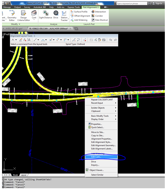
Be sure to adjust your rail gauge. After that you can again right-click and select "Edit Cant" from the selections shown below. NOTE: If you are not similar with rail terms, "cant" is the equivalent of "superelevation".
Image 3
The Cant Wizard will open if no cant has already been applied. You will be prompted to input the type of rail pivot method (location where cant is applied about). This will also be the hold point from the profile.
Image 4
Adjust any known design settings parameters in the following screen:
If you have already gone through this process you should be able to open up right to the editor (shown below). Applying cant goes beyond the scope of this posting, but if the cant has
already been determined you can adjust the numbers right in the table to
Applied Cant.
Image 6
The image below shows (from top to bottom):
- proposed and existing profiles
- cant view table
- alignment with surface and sample lines
Image 7
Screen below shows 3 elevations, after zooming into the Cant View table. Left Rail, Centerline, Right Rail
Image 8
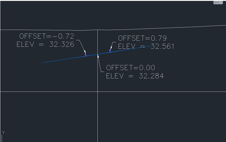
Create a sample lines, and possibly sheets, as explained in my previous post. Check the elevations are being applied to the low rail. A section view cut from a sample yields the image below.
Image 9
Image 10
Note the profile view (below) agrees with lower top of rail at Sta 0+956.65 = 32.32 m Elev as shown on the section.
Image 11
You now have the the beginning components to model your railway. Complete the details of the tie-in and create your cross-sections, if required, using Creating Cross-Section Sheets.
Hope you find that helpful! Thanks for reading.


