Brief Career Bio

- George Koumoutsidis
- Civil Engineer with a Masters Degree in Civil Engineering (Transportation). I also hold a B.Sc. in Civil Engineering and Geomatics. I am licensed as a Professional Engineer in both Canada and the United States.
Thursday, February 10, 2011
Right-Click C3D Commands options unavailable.
Just a a quick note of a problem I ran into today. If you find you can't bring up your C3D commands via a right-click, check to see "PICKFIRST" is set to "1".
Tuesday, February 8, 2011
Modeling a Highway Gore Area
In this session, the intention is to show how to corridor model something as shown below.


 Clink on the Target dialogue box for the region you want to adjust.


When modeling a converging roadway you should pick the areas you want to model into each corridor. This may be governed by the pavement structural sections you want to employ on the ramps. In this example, I chose the breaks of 3 individual corridors as shown above. In this case there is a 4-lane divided highway (principal road), an on ramp and an off ramp. The white lines show the breaks in the corridor. The ramp hatching and yellow hatching will be modeled in separate corridors. The reasons these areas were chosen were based on a number of factors including superelevation and pavement structural section. I won’t get into that discussion here. That should be determined on a case by case basis. Furthermore, you may find that the original dissection doesn’t work as well as an alternate.

The ultimate arrangement should produce a cross-section that likes similar to this:

The cross-section above shows corridor materials for the principal road only. I will run through a quick explanation how to get to this point, assuming you have profiles for all three roadways and the horizontal arrangement set.
Ready….
First pick the region which you intend to model. The location shown below (between the two blue lines) was chosen based on the following:
1) West end, where the bullnose meets between the onramp and the principal roadway.
2) East end, where the superelevation of the ramps can be blended back to the required superelevations of the principal roadway.

Now that we have the chosen area, let’s build an assembly to match the condition. Ultimately, it will look as shown here:

We are only modeling 60m of roadway. I realize that this is a short section of the roadway, but a critical one. I’ll give a quick explanation of the chosen sub-assemblies is as follows:
From the center to the left:
a) A small width for where the edge of median pavement is to be. Default is 0.8m but giving it a separate subassembly allows us to target the median pavement edge, in the event the median has to be widened (possibly from using a transition to allow more Stopping Sight Distance along a curve). You have to use “LaneInsideSuper…” if you want the super to take effect in this area.

b) An inside lane. Again, be sure to use “LaneInsideSuper…”. There is a 2% default cross-fall, but this will be overridden if you have superelevation defined for the roadway

c) An outside Lane. (Notice Subassembly allows for super - Subassembly.LaneOutsideSuperMultiLayer)

d) The last section of pavement will allow pavement through the gore area. Notice the given name of the sub assembly. The 0.5m width is irrelevant because it will be used targeted by means of an alignment or feature line.

e) The last component on the left side is LinkSlopeToSurface. This reason for including this is to close the corridor off vertically, so that surfaces created won’t extend beyond into adjacent roadways, consequently throwing off earthwork quantity calculations (possibly another post).
The right side of the template is the same, with the exception of the paved gore area. The paved gore area of the onramp will be built in with the onramp.
Once you have your targets set (either as feature lines, alignment or polylines), you can continue modeling and setting your target parameters. In this case, I used a feature line as depicted below:

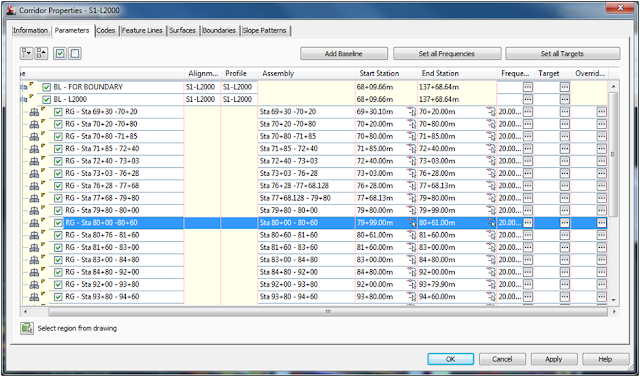
Continue to the Corridor model and select the region which you want to work in.


As you can see from above, I used a feature line to target the LEFTGOREAREA. This was a 3D feature line extracted from the offramp corridor. Also, as shown above, notice the same feature line is used both as an Offset Target and an Elevation Target.
That additional modeling will get you to this point…..

Eventually you can model the two adjacent roadways and shown them on the cross-section, as shown in earlier image.
There is a lot to consider in this area. I don't want to overwhelm, or gloss over an important step, so I made this as straightforward as possible. If you have any questions, just let me know. I will try my best to respond. I hope to give a more detailed discussion of "closing off" corridors for the purpose of extracting earthwork quantities from the software.
Hoping your crashes are to a minimum!
G.
Subscribe to:
Comments (Atom)