
There are several things to discuss regarding C3D with respect to its sharing capacities and archiving. As the software's popularity increases, I heed a word of caution. Be sure to have a planned out structure of all the drawings/models you intend on having, and within each, determine what type of details plan on storing in them - both now and much later into the project. I may attempt to add notes from the types of discussions I've had and problems that some design teams have incurred in subsequent posts.
I digress.....
The following example is to detail an option of adding a berm on the outer extents of your corridor, when the ditches you model do not provide proper containment and conveyance.
Your design calls for cut ditches, but the fill on the foreslope only allow for half the depth. In other words, the ditch does not have the capacity to convey the runoff to the next tributary.
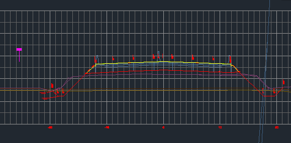
Image 1
Image 1 shows the corridor modelled with ditches. Let's concentrate on the left-side.

Image 2
In the screen capture above you see the ditch has minimal depth and the ditch requirement based on storm calculations requires at least a 0.8m depth ditch. This ditch depth is only approx half meter (0.92-0.45). We require additional fill to provide a berm that can contain the storm water. To do this it's a simple as adding another target.
I scanned the cross-sections to determine were depth requirements weren't being met. I just drew a line (white) within the corridor representing this range.

Image 3
Convert this to a Feature Line. Btw, you don't have to worry about a precise location for it. It will be used more in a true/false fashion. If the line is found in this section a berm is to be modeled, if not....no berm. How do we do this? Just like we've done before - using conditional targets.
Add the conditional targets to the desired location on the assembly. In this case I added them to them bottom left side of the ditch.

Image 4
Notice the additional generic links on the "Target Found" condition. This is what builds up the berm, if the feature line is targeted through that section. Open up Target Parameters and populate the Object Name field with the feature line you created. I named mine "BERM LOCATION (3)". Be sure to choose the object for both the Found and Not Found conditions.
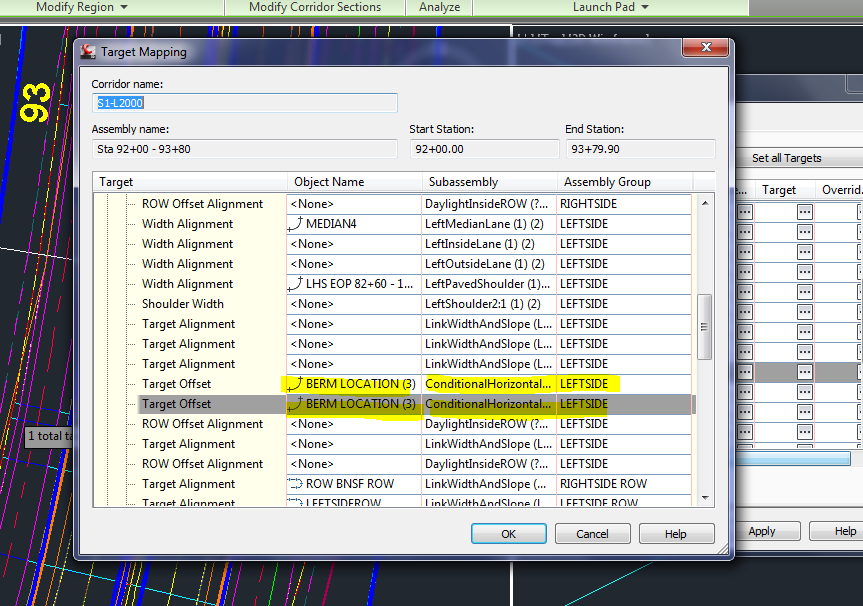
Image 5
Refresh the corridor and with any luck you'll see the berm addition.

Image 6
You'll also notice in the corridor itself that the model bulges out coinciding with the location of the feature line (blue grips below)

Image 7
Hope you found this useful and possibly can utilize this concept in similar manners. Remember, the feature line doesn't have to placed in the exact location, you just have to show intent of what you want to happen. The corridor modelling takes care of the rest.
George