Pages

Brief Career Bio

My photo
Civil Engineer with a Masters Degree in Civil Engineering (Transportation). I also hold a B.Sc. in Civil Engineering and Geomatics. I am licensed as a Professional Engineer in both Canada and the United States.

Blogger Contact

Feedback kindly welcome. Email me!

Thursday, August 7, 2014

Modelling Rail Data in 2014


As can be seen between posting dates, I have taken a significant amount of time from posting to this blog.  As career responsibilities change, my time spent directly on the software fluctuates.  Some recent moves have brought me closer to working with Rail, and after a somewhat feeble attempt to master Microstation and Bentley Powerail, I noticed some rail features in Civil 3D 2014.  To say the least, building off what I was already familiar with was going to be easier than learning two different software simultaneously.

While I certainly don't get any Civil 3D kickbacks, and I'm not always pleased with how the software reacts and some developing frivolous changes, this one was a welcome component.  So consider this posting a kudos to AutoDesk as well as in information session for modelling rails in using the software.


To begin modelling your rail in Civil 3D, ensure you have an alignment, design profile and an existing surface.

Image1


Be sure you have your alignment defined as "Rail".  You can do this during creation or right-click and change the properties.

Image 2

Be sure to adjust your rail gauge.   After that you can again right-click and select "Edit Cant" from the selections shown below. NOTE:   If you are not similar with rail terms, "cant" is the equivalent of "superelevation".
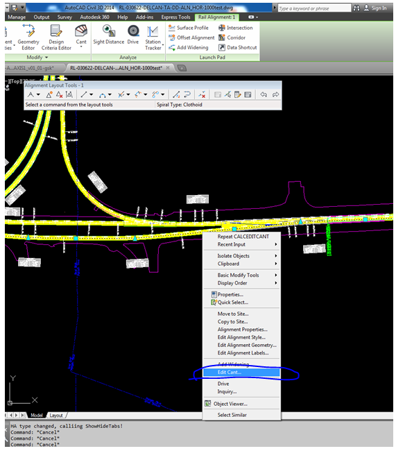
Image 3

The Cant Wizard will open if no cant has already been applied.  You will be prompted to input the type of rail pivot method (location where cant is applied about).  This will also be the hold point from the profile.

 Image 4

Adjust any known design settings parameters in the following screen:

Image 5
If you have already gone through this process you should be able to open up right to the editor (shown below). Applying cant goes beyond the scope of this posting, but if the cant has already been determined you can adjust the numbers right in the table to Applied Cant.
  
 Image 6

The image below shows (from top to bottom):
  1. proposed and existing profiles
  2. cant view table
  3. alignment with surface and sample lines

 Image 7


Screen below shows 3 elevations, after zooming into the Cant View table.  Left Rail, Centerline, Right Rail

 Image 8

Create a sample lines, and possibly sheets, as explained in my previous post.  Check the elevations are being applied to the low rail.  A section view cut from a sample yields the image below.

Image 9

And a blow-up detail of the image above, here:
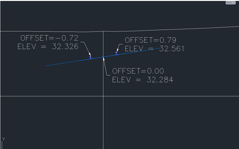
Image 10

Note the profile view (below) agrees with lower top of rail at Sta 0+956.65 = 32.32 m Elev as shown on the section.

Image 11

You now have the the beginning components to model your railway.  Complete the details of the tie-in and create your cross-sections, if required, using Creating Cross-Section Sheets.

Hope you find that helpful!  Thanks for reading.

Thursday, January 30, 2014

Another Elusive Annotative Text Exercise


Hey Everyone!


It’s been quite a while since my last recent, but breathe easy ;) I am still around.

Fortunatley (or unfortnatley depending on perspective) the last project I was on I had less to do with the set up.  I still had to delve into some of the drawings of course and this was one of the many issues that caused me great headaches.  This next post was something that I believe to be a systemic approach with respect to drawings setup, but the post explains a work around after the drawing setup is a fail.

***I CANNOT STRESS DRAWING COLLABORATION SETUP ENOUGH.  THE DESIGN TEAM NEEDS TO CONSIDER WHAT SHOULD BE IN FILES AND HOW THEY WILL EFFECT THE END USER, ESPECIALLY DURING THE CONSTRUCTION SERVICES PORTION.  DRAWING NEED TO BE FLEXIBLE AND EFFICIENT LATER IN THE PROJECT (PARTICULARLY FOR DESIGN-BUILD PROJECTS)

In this post, I am going to walk the reader (hopefully you) what do in the case when there is text in design files. 

NOTE:  THIS IS SOMETHING I ATTEMPT TO PROTEST DURING FILE SETUP.  NO DESIGN TEXT IN THE XREF (topography is fine).  THIS IS A COMPLETELY DIFFERENT TOPIC AND CAN BE DISCUSSED AS A SIDEBAR CONVERSION.

Ok….let me paint the picture.  A design file with storm/sanitary  sewer is created and referenced in a package for a Construction Package.  Civil 3D text of pipe sizes  are dynamic and included in the design file.  The Construction sheet is to plot at 1:500.  A realization was made, that the proposed works which will go under a set of rail tracks, will require permit.  The drawing must be recreated and as luck would have it the scale is to be 1:250.  Not only will you have to ensure the leaders’ positions are scaled correctly, you’ll also notice that all your text may not have been Civil 3D annotative text.  The Civil 3D labels scales but the additional notes don’t.  What a mess!

Image 1 below shows the drawings at the 1:250 scale.  Notice that most of the text is scaled to a professional level, but the “TRACK LOAD INFLUENCE ZONE”, “MIN 0.3…” and “XXX STM” sizes appears as though a Jeff Foxworthy fifth grader added them.  Now, if text wasn’t in the design files you wouldn’t have this problem, but it’s too late for that so let’s look at a duct tape fix.


Image 2 shows how are the labels appear the same size in the design file, prior to any viewports being added.

Now in the design file.  If you select the text (“TRACK…” text).  You’ll note that the text is not Annotative.


Image 4 shows you how to give that text a flexibility to show annotatively in future viewports.  In our case we need to set up to be shown at 1:250.  Follow the red marking below to add your desired scale(s).


When you get back into the design file, you can select the text and see a faint second writing of the same text – Image 5.  If you see this, you’re on the right track.


Intuitively, you think you be finished here, but that`s not the case.  You`ll have to actually select into the text box, select the text and see that the text highlighted is being marked as Annotative – Image 6 and 7.


This last process it quite convoluted and sometimes the text box states that it is already annotative, but when you actually highlight the text it doesn’t show the Annotative option.  Be sure this selected. 

Now save your design file, go back to your sheetfile and regenerate.  You may have to work on justification and other things pertaining to a location, but understand this is a last resort when you’re trying to recreate things without making too many changes to a drawing.

Hope that helps.