
One of the biggest obstacles to working with Civil 3D is deciding how to set up your files. You have to decide a plan of attack on what you will do in each model and/or drawing.
The great benefit of Civil 3D lies in the ability to have labels (information tags) update once you make changes to the model.
The following post will show an example of how I used a Civil 3D grading model to produce a dynamic paving plan. Just like everything in life...."there's more than one way to skin a cat", so take what you will from the post. It's an idea and if you can improve on it, even better.
Now how do you get from here:

Image 1
To here:

Image 2
That ultimately brings you to here:

Image 3
And a closer inspection:

Image 4
The first part of this process is having a surface developed. Take a look at the mess in Image 1 above. This is the working model. This model-drawing will have ongoing site grading changes occurring. This is where the actual data is being contained, for the purpose of displaying spot elevations as shown in Image 4. That being said, the drawing-model is not used directly for production drawings.
In addition to the actual drawing-model (you can call this FG.dwg for simplicity), I used:
-a site reference basefile (site.dwg)
Containing all curbs lines, edge of pavements, building footprints, etc.
-a site paving plan (paving.dwg)
Containing all construction/paving joints
-a spot shot plan (elevations.dwg), as shown in Image 2
Containing nothing but the paving spot elevation
Of course you'll probably have more, but this is all I'll introduce for showing the paving plan elements.
NOTE: Why is the site paving plan separated from the site reference basefile? Well, for this project there were so many concrete joints that modifying it it was best to have this drawing separately accessible from all the other drawings.
With the model already complete (which we know is never really complete, because there WILL always be changes), start an elevations.dwg file from your applicable template.
First thing to be sure of is that your project working file path is set up properly.

Image 5
Notice the "\model_files\c3d" (in my case pathed back the "C" drive")
Be sure to go into your model drawing (FG.dwg) and shortcut the surface out to the project directory "Data Shortcuts". Notice above, there are currently no shortcutted surfaces (ie. no "+"-sign next to the shortcut surface list).
In the model drawing (eg. FG.dwg) , right-click on "Data Shortcuts" on the Toolspace, then select "Create Data Shortcuts". When prompted, select the surface you would like to shortcut to the project directory (ie FG.dwg). (Not shown here.)
Notice below that the surface is now shown in the shortcut list. This will show in either the FG.dwg or the elevation.dwg.

Image 6
Switch back to the elevations.dwg and "Create Reference" of the FG surface.
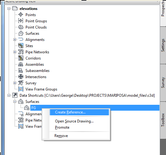
Image 7
IMPORTANT: Be sure to set your surface style to a non-display style, otherwise you will be battling TIN or contour lines (maybe both). The surface will be there, don't worry. I'll show you later.
XREF (preferably "overlay") the site.dwg and the paving.dwg into the elevations.dwg.

Image 8
The site.dwg and the paving.dwg are strictly 2D drawings.
With the 2D drawings now allowing you to see where the horizontal location of the surface is on the screen, you can zoom in and inspect elevations. If you have your tool tips display "on" and you hover your mouse over an area where the surface is, you'll see the proposed elevation at that location.

Image 9
Notice above, FG=4040.117'.
Hard part is over. Now you can begin to populate this drawing with spot elevations.
From the Ribbon as shown - below:

Image 10
Start picking/clicking the locations where the construction joints are on the plan. You will have to modify the location of the labels, if you change the location of the joints. Common sense of course, right?

Image 11
You'll notice the label above looks different than the labels shown in Image 4 earlier. This I will tackle in another post if I get any feedback, but this should be something that may give you an idea how to get started with a paving plan.
The beauty here is you can now modify the grading drawing (FG.dwg), and the labels will update themselves, eliminating tedious Cad changes!!! Yes!
Again, any feedback is greatly appreciated and I hope this help!
George
One last warning------if you change your construction joints, don't forget to change your grade breaks in your model drawing (FG.dwg).